I have been thinking lately about converting a computer power supply over for benchtop use. I’ve read several online articles describing how to do it but haven’t gone out to the shop and removed one from on of my old surplus systems yet. Today I decided to go pull one out and start looking into what I needed to do. I have some hot-swappable power supplies from an old Dell 2500 server and so I got one out of the box and realized that unlike the articles I had read online I wouldn’t have to perform any physical modifications to the power supply. All of the required connections are already accessible and no wires need to be bundled together.
For a good test I decided to use the power supply on one of my Raspberry Pis. The power supply has connections for +12V, +5V, and +3.3V. Since this is a computer power supply it’s definitely regulated well so I don’t need to build any additional circuitry to make it work.
I did this today just as a proof-of-concept so I didn’t make anything permanent so I’ll leave the final build details to you. Please remember that you are dealing with 120 volts (or 240 volts, depending on your location) and take the appropriate safety precautions. You have been warned!
Here is the list of items I used:
- Dell ATSN Model 7000240-0000 Power Supply
- Standard 3-prong Computer Power Cord
- 3-inch Female-to-Female Jumpers (from SchmartBoard) – 2 Total
- Enercell Replacement Adaptaplug Socket (Radio Shack part #273-350)
- Enercell Micro USB Adaptaplug (Radio Shack part #273-413)
- Raspberry Pi
The first thing I had to determine was the pinout of the power supply. As you can see in the following picture, there are a total of 32 individual connection points on the rear of the power supply. Eight are power connectors and 24 are signal connectors used by the Dell server to monitor the power supply status.

Dell 7000240 Power Supply – Rear
There are no markings on the outside of the case showing what any of the connectors are so I needed to open it and examine the interior as most power supplies use different colors of wire to indicate their purpose.
There are eight screws that need to be removed in order to open the case. Two on the top at the front of the power supply.

Dell 7000240 Power Supply – Top
Three on the right side along the top of the case.

Dell 7000240 Power Supply – Right Side
And three on the left side along the top.
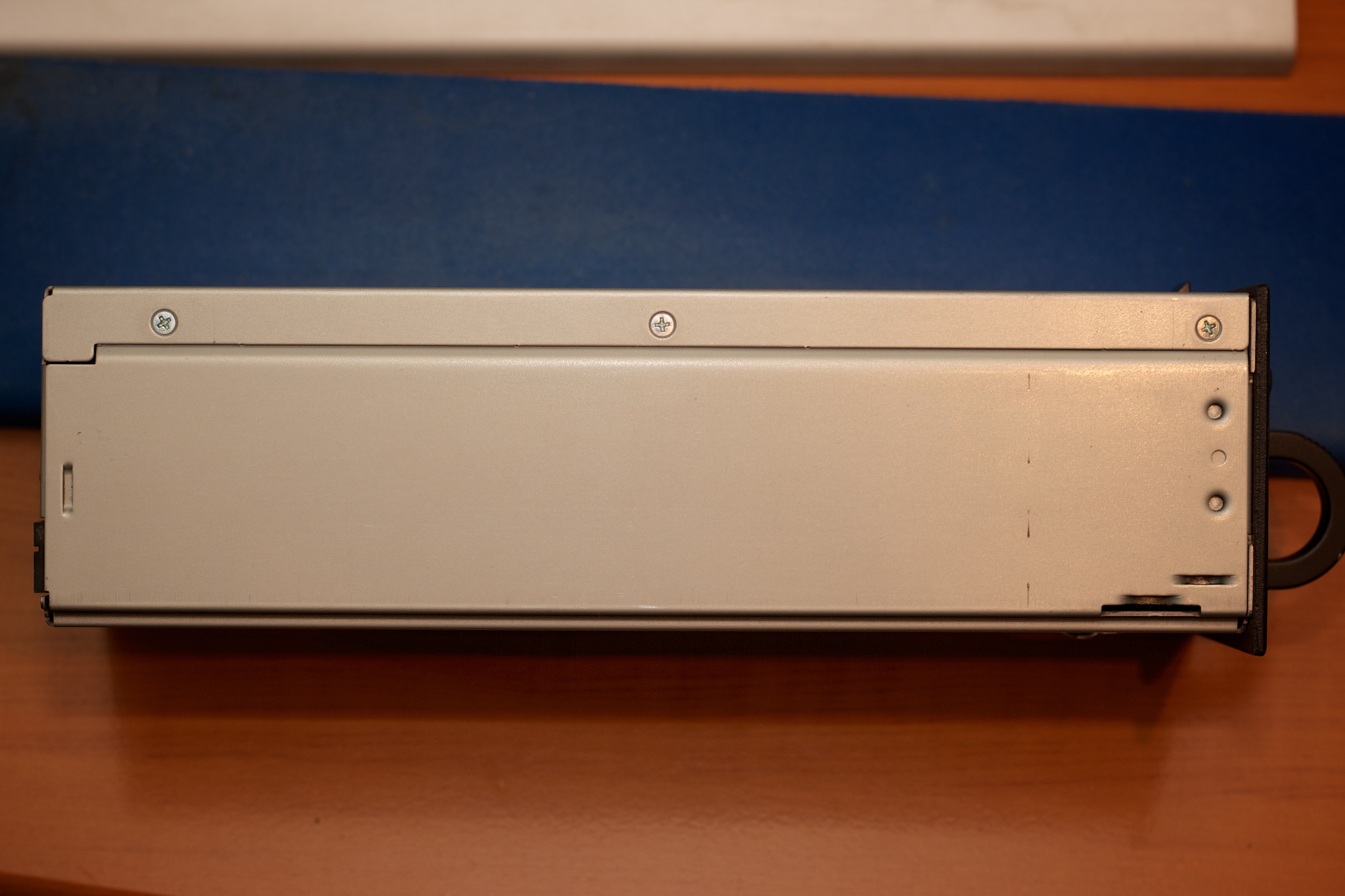
Dell 7000240 Power Supply – Left Side
Once these eight screws are removed you should be able to lift straight up on the top of the case to open it. The rear panel holding the two exhaust fans is part of the same piece as the top and will come off as well. There will be a bundle of wires from the main board to the two fans. It’s not very long but you should be able to lay the top of the case over to the rear of the power supply.

Dell 7000240 Power Supply – Main Board Screws
Here we take the first look at the interior of the power supply. There are two boards. The main board on the bottom of the case and a secondary board mounted on the right wall of the case. There are no markings to be seen that indicate the use of any of the connectors. The only clue seen is the screw in the lower center of the picture above. The screw is attached to a metal standoff on the bottom of the case under the main board. This indicates it is the main ground and it is connected to the third pin from the left in the picture of the rear of the power supply in the first picture after the parts list above. It’s only logical to conclude that the other two pins on that part of the connector are the line and neutral judging by the size of their traces with line being the left-most pin and the neutral being the center pin of the three. I found an article over on http://www.rcgroups.com which shows another Dell server power supply with a similar pinout which lends support to this assumption. However, there’s no indication on the purpose of the individual signals pins nor of the five remaining power pins.
Now it’s time to check the bottom of the main board. First we need to remove the two screws holding down the main board. They are in the upper and lower center sections of the last picture above. Once those are removed then there is the single screw holding the secondary card in place. Take a look at the following picture of the secondary board on the right inside wall of the case.

Dell 7000240 Power Supply – Secondary Board Screw
Once that screw is removed you should be able to left the boards slightly and slide them backward about an inch or two. You will need to pull out a bit on the shield behind the secondary board to get it away from the standoff. You may also have to do the same for the shield underneath the rear portion of the main board. Once you have pulled the boards back, turn the power supply over to inspect the bottom of the main board.

Dell 7000240 Power Supply – Main Board – Bottom Rear
As you can see here, there are no helpful markings there either. We will likely need to use a meter to determine the voltages on the remaining power pins and maybe the purpose of the individual signal pins.
Before we start checking pins let’s put the power supply back together. First, make sure the shield under the rear of the main board is in place. The two holes in the shield fit over the two board standoffs and it should stay in place with very little trouble. Then look for the main board guides on the right and left sides of the case toward the front.

Dell 7000240 Power Supply – Main Board Guide – Left Front
This picture shows how they are staggered. Place the leading edge of the main card on top of the rear guide and then slide the board forward and underneath the front guide. At this point make sure the screwholes on the main board line up with the standoffs underneath and that the screwholes on the secondary board lines up with its standoff. Make sure the hole of the shield behind the secondary board is placed on the standoff.

Dell 7000240 Power Supply – Secondary Board Standoff
Once all three screwholes are aligned with their standoffs, replace the screws to hold them in place.
Now we need to close up the case. Lift the top of the case from behind the case and fold it over to align the case guide slots.
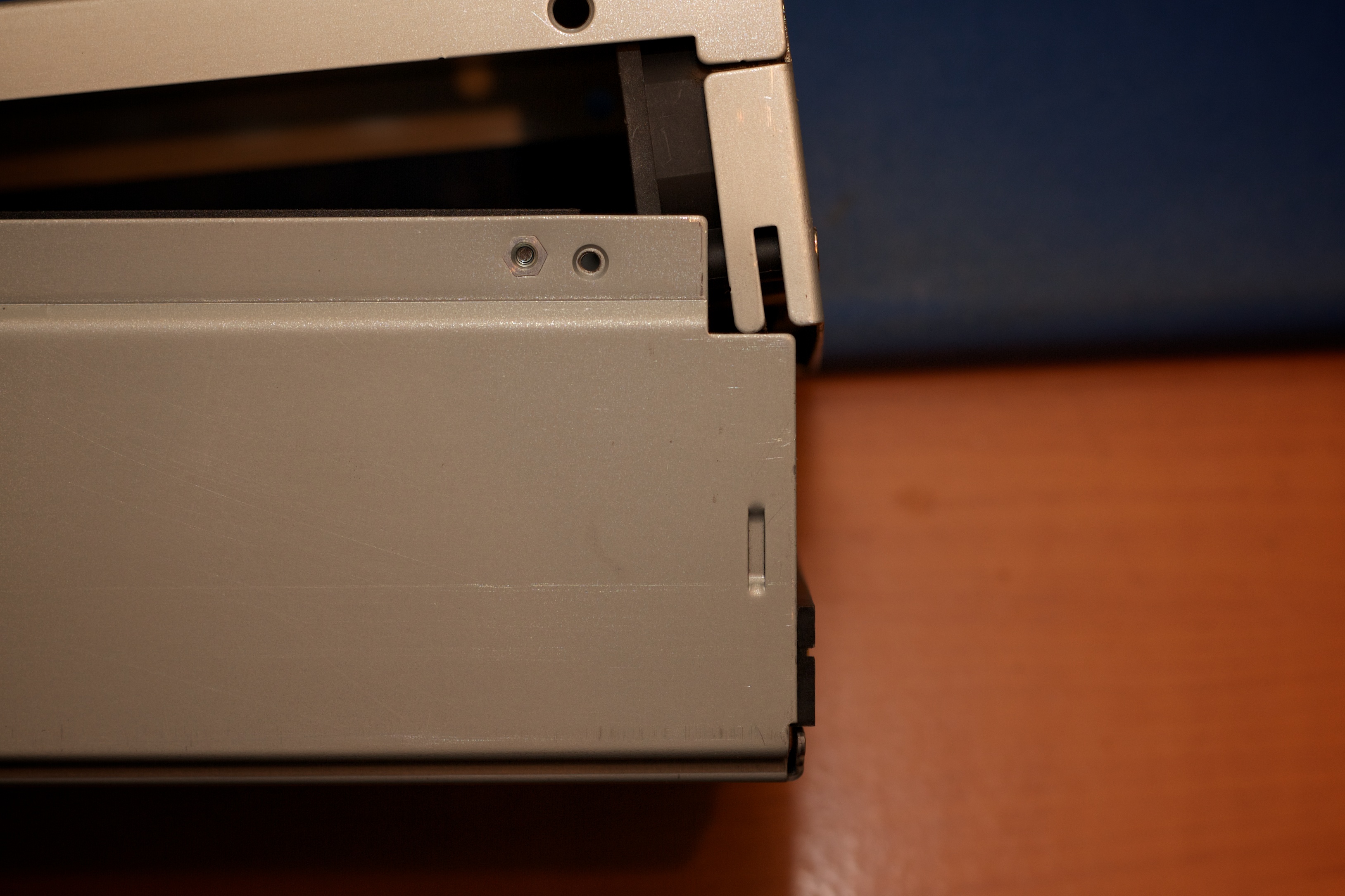
Dell 7000240 Power Supply – Rear Case Guide
Once the slots are lined up, lower the top of the case straight down into place and make sure the screw holes line up properly. Then replace the eight screws. Each of the eight screws is the same as the others so you don’t need to worry about swapping any around.
Once the case is reassembled we can turn our attention to the task of preparing the mains power cord.
First, cut off the female end of the cord.

Power Cord – Female Plug Removed
Next, take a utility knife and carefully remove about 1.5″ of the outer insulation, taking care to avoid nicking the conductors inside. Here’s what you end up with after removing the outer insulation.

Power Cord – Outer Insulation Removed
All we are concerned with are the white, black, and green wires. The nylon strings and the uninsulated wire can be removed with wire cutters. Then, strip off 0.5″ of the insulation on the black, white, and green wires.

Power Cord – Stripped
Now that we’ve stripped the wires we can temporarily attach them to the mains power pins on the back of the power supply. The three mains pins are on the left. The first is the line connection. Connect the black wire here. The second is the neutral connection. Connect the white wire here. The third ping is the ground connection. Connect the green wire here. Once you have done that then plug in the power cord. You will hear the two exhaust fans start. Then take a look at the front panel. A single green indicator is lit showing the power supply is in standby mode.
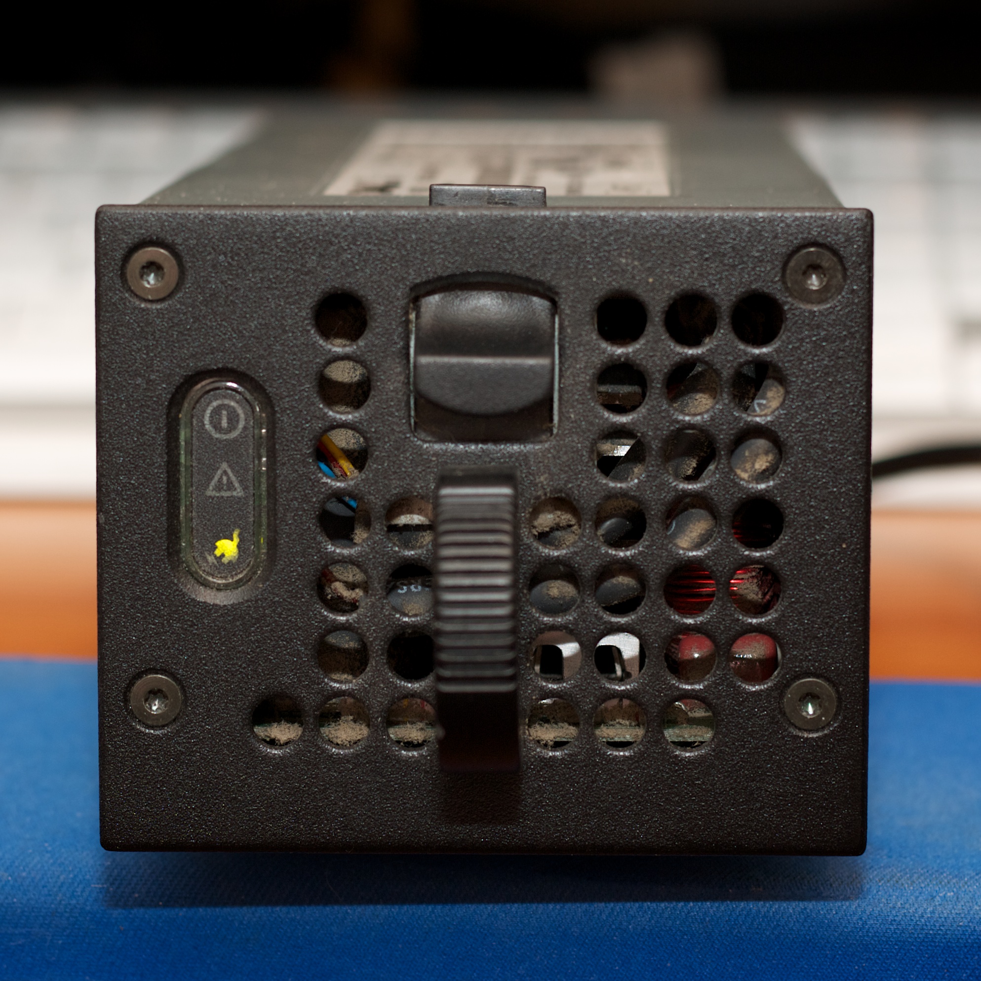
Dell 7000240 Power Supply – Front – Standby Power
We confirm this by checking the DC power connections, the five connections to the right on the rear. I used my meter at checked the pins and provided the results below.
Pins 1 & 2 – +0.0V
Pins 1 & 3 – +0.49V
Pins 1 & 4 – +0.13V
Pins 1 & 5 – +0.11V
Pins 2 & 3 – +0.49V
Pins 2 & 4 – +0.13V
Pins 2 & 5 – +0.11V
Pins 3 & 4 – -0.36V
Pins 3 & 5 – -0.02V
At this point it appears that pins 1 & 2 may be the ground pins. Considering the low voltage on the other pins than what was suspected indicates that the power supply is in standby mode. We will need to figure out which of the signal pins to bridge together to get the power supply to completely turn on and be ready. Quite fortunately, I found another article on http://www.rcgroups.com that showed the mapping of these pins so I didn’t have to do the work.
The signal pins are arranged in four rows of six pins each. There are only two pair of pins to be connected to one another. Row 2/Pin 3 and Row 4/Pin 3 need to be connected to Row 4/Pin 5 and Row 4/Pin 6. These last two pins are ground pins so it doesn’t matter which of the first two pins are attached to which of the last two pins. Make those connections with the two 3″ female-to-female jumpers. If you still have the power supply plugged into mains power when you do this then you will hear the fans kick into a higher speed and maybe a few clicks from inside the power supply.
The front of the power supply should then look like the following picture.

Dell 7000240 Power Supply – Front – Power Ready
Now we can check the DC connections again. Here are the results:
Pins 1 & 2 – +0.0V
Pins 1 & 3 – +11.93V
Pins 1 & 4 – +5.10V
Pins 1 & 5 – +3.35V
Pins 2 & 3 – +11.93V
Pins 2 & 4 – +5.10V
Pins 2 & 5 – +3.35V
Pins 3 & 4 – -8.58V
Pins 3 & 5 – -1.74V
This shows that the pins are as follows:
Pins 1 & 2 – 0V (Ground)
Pin 3 – +12V
Pin 4 – +5V
Pin 5 – +3.3V
Now it’s time to connect it to the Raspberry for a smoke test. First I took the Enercell Replacement Adaptaplug Socket and connected the wire for the Pin of the socket to power supply pin 4. This is the wire with ribbed insulation. I held it in place with an alligator clip. Next I connected the other lead to a ground pin with another alligator clip.
At this point it is very important to verify the polarity of the Enercell Socket. Simply use the meter and insert the red lead into the “tip” socket and the black lead into the other socket. The meter read +5.10V.
Then I took the Enercell Micro USB Adaptaplug and plugged it into the Adaptaplug Socket and ensured that the “+” and the “TIP” indicators were aligned. Once that was done I connected it to my Raspberry Pi and up it came without any issue.

Dell 7000240 Power Supply – Power Connections

Dell 7000240 Power Supply – Powering Raspberry Pi
Finally, here are the specs on the power supply decal.
Input: 100-240V, 50/60 Hz, Max AC Current 5A
Output: +12V, 19A
+5V, 19A
+3.3V, 18A
-12V, 0.8A
+5VFP, 1A
Total Output Power Not to Exceed 300W.
Ambient Temperature 40 degrees C MAX
3.3 and 5v Combined Power Not To Exceed 125W
I hope you have found this article to be intriguing and helpful. Please feel free to leave a comment.
Keith

Thanks for the excellent write-up! It sure saved me a lot of time!
I’m glad to hear it. Thanks for reading!
Keith
Thank you so much! I was really stuck on what to do and this helped a TON!! These power supply’s are great and I picked one up for $9 at a electronics store. It makes an awesome power source for all of my Halloween madness:) Thank you!
Glad to hear it!
Hello! I try to convert 3 redundant power supply dell poweredge 2500 ( same power supply than you) to atx withoout luck. Can you help me?
I wont modifier only one power supply.
Thanks
Pablo
Barcelona (Spain)
Are you looking to add ATX-style connectors? ATX is actually the form factor of the PSU itself and 7200240 is too large for fit into an ATX case.
Hi! Thank you so much!
But what about function of the other pins of central connector?
Do you have any information about this?
Sorry. I don’t have that information. Be sure to let me know if you’re able to find it!
Keith
Thank you for this post it saved me a lot of time on the project im currently working on but i only need to conect row 2 pin 3 to ground and it powered up.
Keith. I have the Dell ATSN 7000240. could you be specific about the connections to the small pins between the AC and DC outputs?
Thanks